
It was time to take the experiments one step further by making a fully functional product. Creating a custom PCB for the electronics seemed quite daunting at first, but then I found som help.
I came across this great youtube tutorial for making a game controller on a custom PCB made by a channel called Danovation. The tutorial can be found here: Arduino Game Controller FULL TUTORIAL. It covers everything required to make a functional XInput (plug and play) game controller using an Arduino micro controller. This tutorial inspired me to try making a game controller of my own.
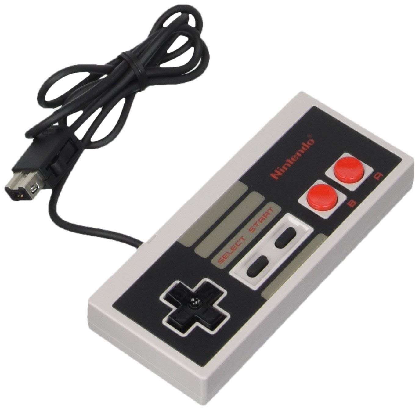
For the design, I thought it would be fun to base the controller on the classic controller for the 8-bit Nintendo Entertainment System (NES), and then take it into modern times by adding more buttons and thumb sticks. This is what the original NES controller looks like for reference:
I started by modeling a mockup of the original NES controller and then progressed to modify that to fit the new buttons and sticks. This took a while to get right and the ergonomics of the finished controller aren’t the greatest, but it’s comfortable…enough :-).
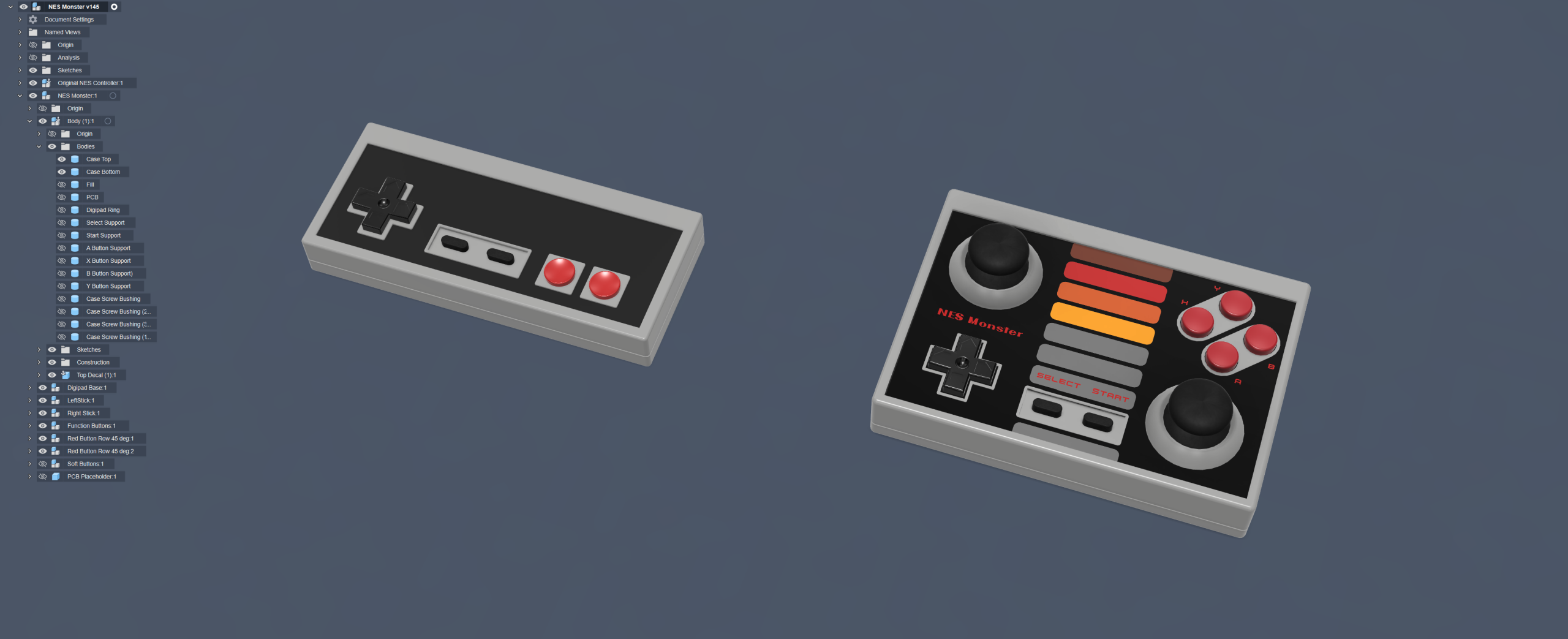
The lower left corner of the controller is exactly the same as the NES controller. The width is also the same as the original, while mine is expanded in height and depth. The depth increase was necessary to fit the thumb sticks, since they are quite high and need extra clearance to rotate freely.
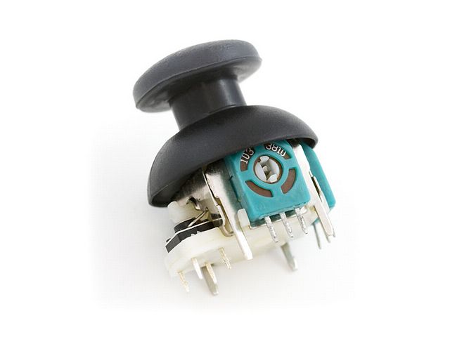
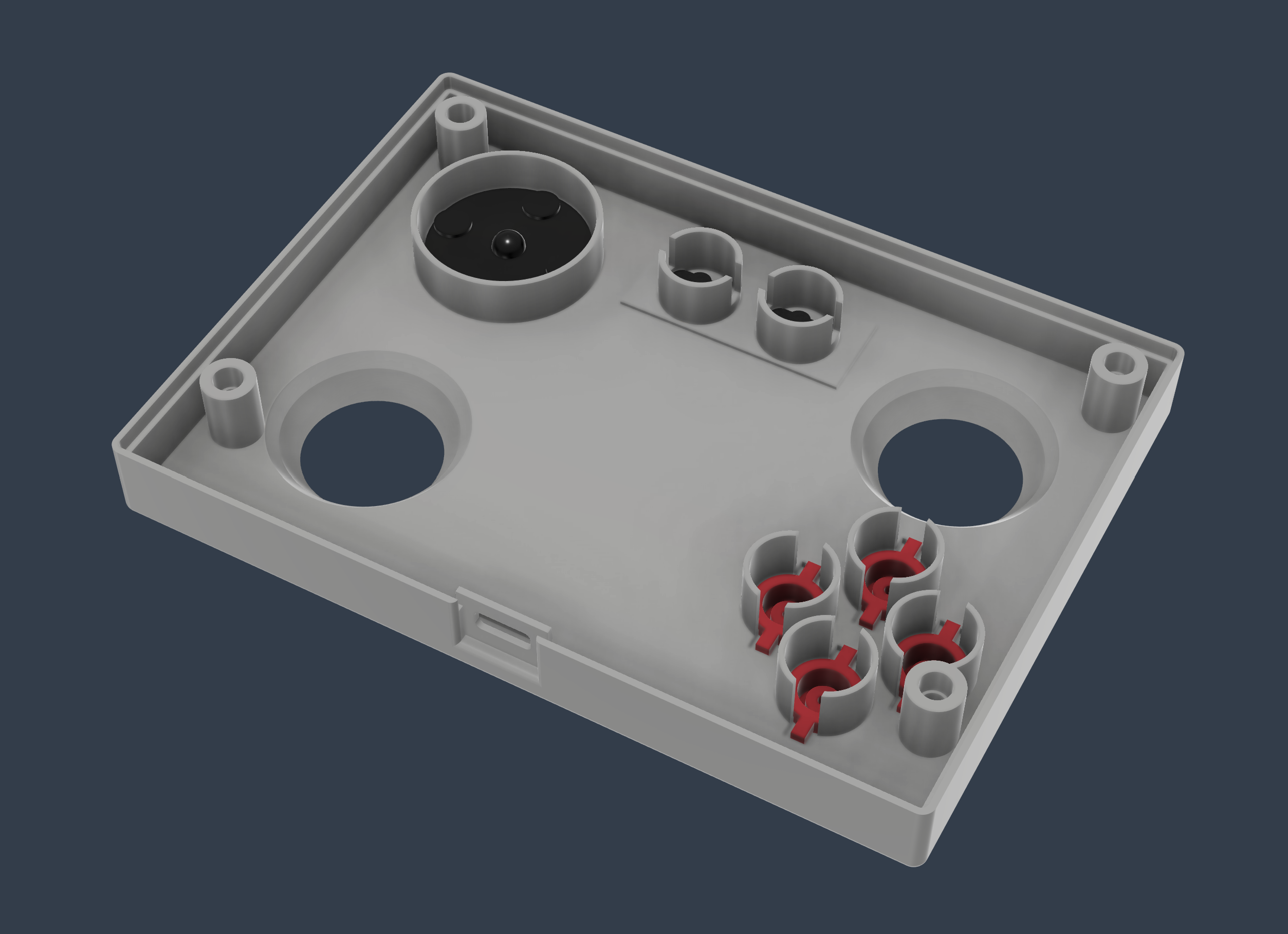
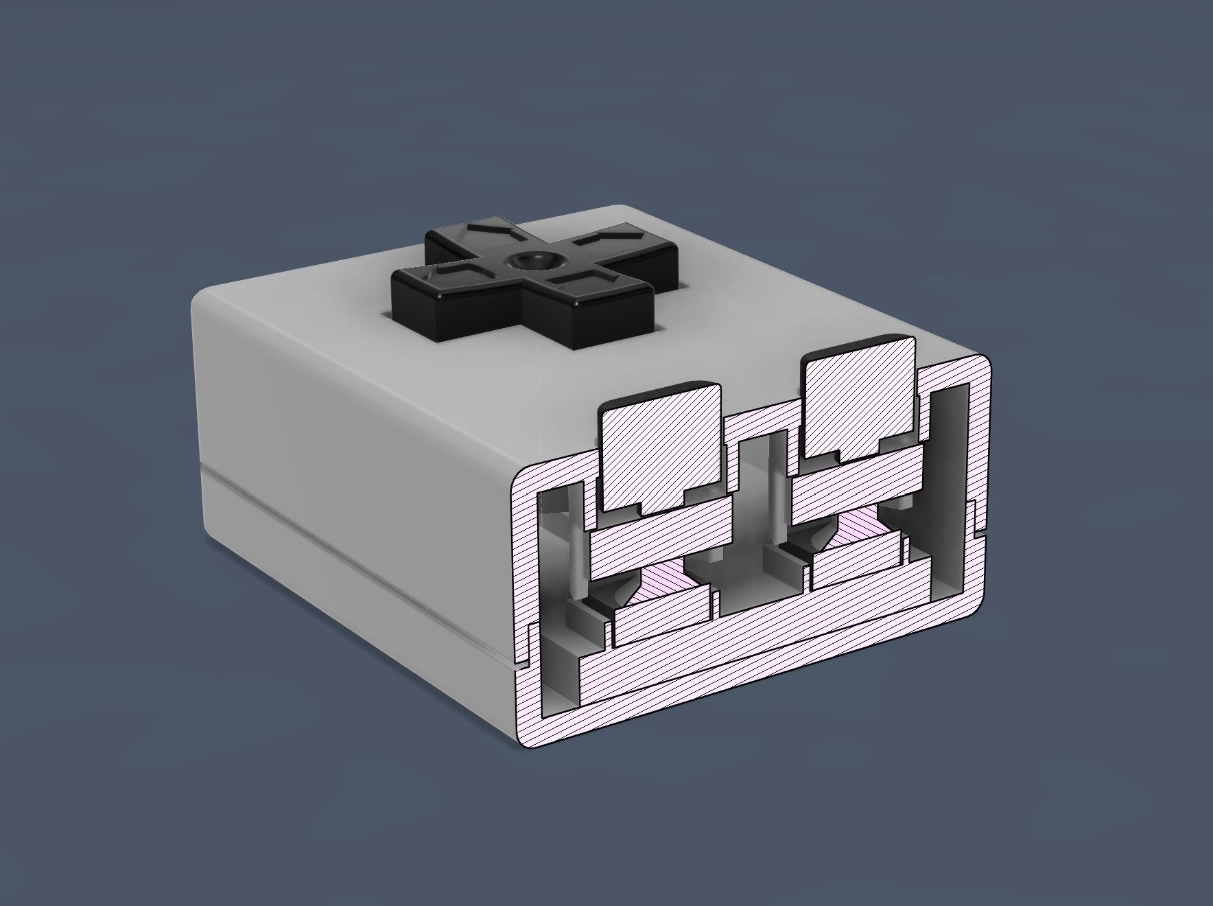
A fair amount of time was spent on the inside of the case, making sure all buttons could reach the PCB mounted switches through guides and extension rods. I used buttons (red and black) from reproduction NES controllers, so no original controllers were harmed in the making of this prototype.
To iterate on the button action without having to print the whole case over and over, I made a mini controller that only had a few buttons and a digipad. This really helped in tweaking the button presses to feel just right.
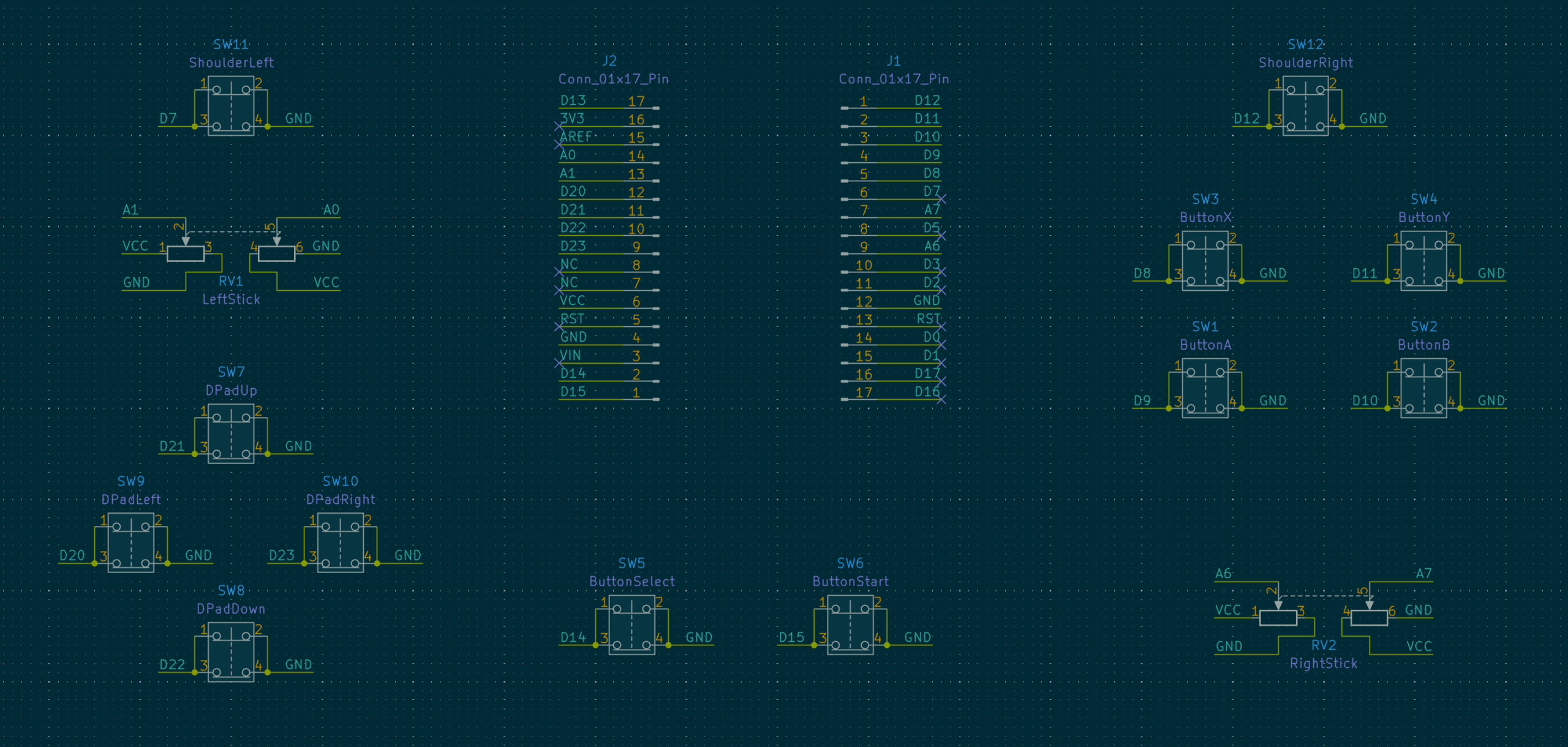
Now that the case was done and the button layout in place, it was time to create the PCB that goes inside. For that I used KiCad, a free to use and very powerful software package. The PCB design is very much based on Danovation’s tutorial with some tweaks here and there. This is what the schematic looks like in KiCad with 10 soft buttons, 2 angled buttons, two joysticks and the pin rows for the Arduino Micro:
Then these components were laid out to match the case design and tracks routed between them in the PCB Editor of KiCad.
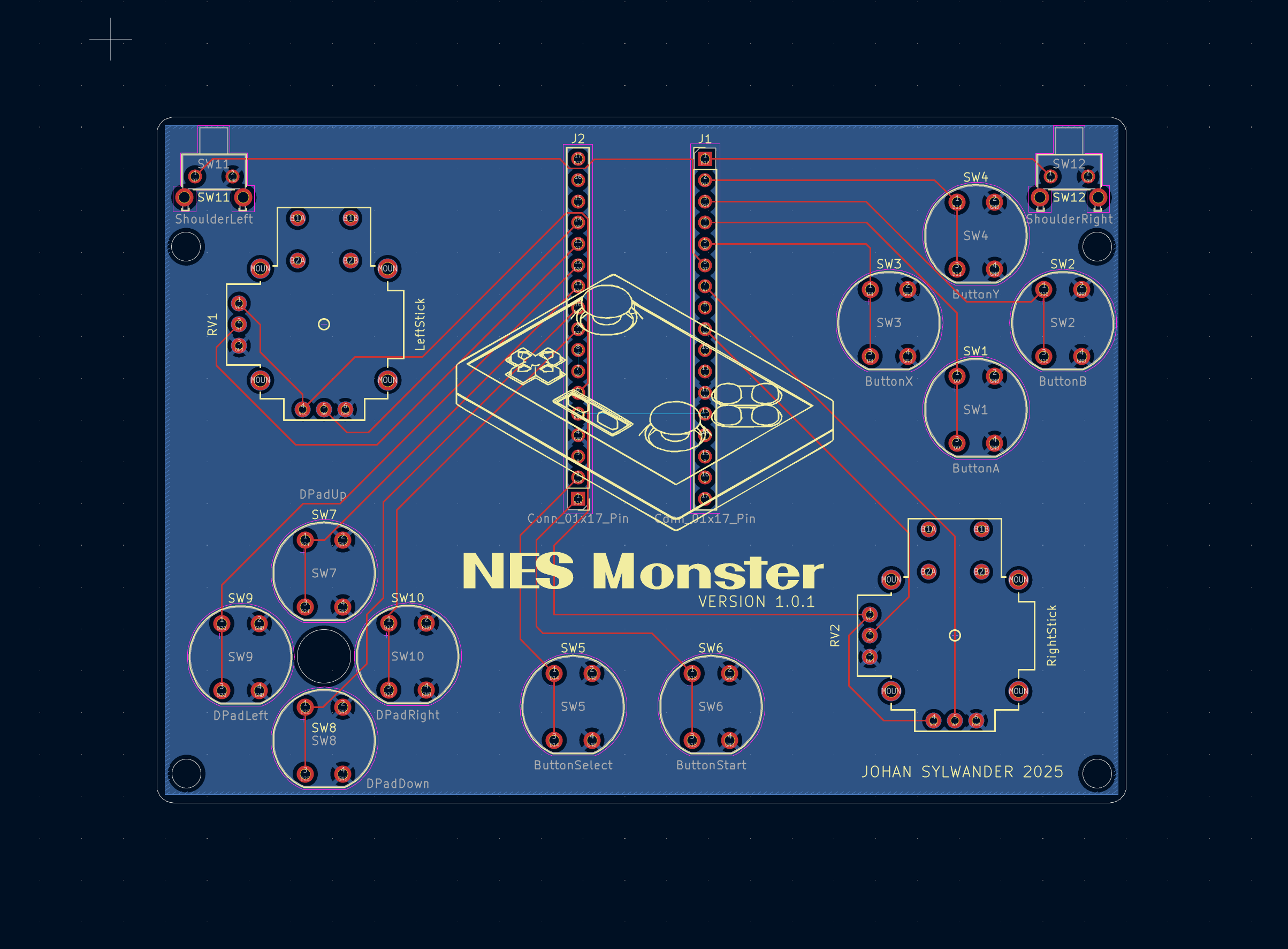
The observant will notice two things on this PCB design:
- The version is 1.0.1, not 1.0.
This is because I made a mistake with the footprints of the buttons on the PCB, using a smaller footprint than the soft button I was using actually had. So I ordered a batch of boards only to find out they had to be scrapped immediately. - There are shoulder buttons (top left and right corners) on the PCB, but not on the controller case.
This project took a bit more time than expected and I just wanted to finish it without having to design a semi complex swivel button for the shoulders. No one will ever know…right?
I used JLCPCB for fabrication of this board and their service was very easy to use and affordable (~$5 for 5 PCBs). The quality of the PCBs when they arrived 3-5 days later was impressive – it really looks like a professional product.
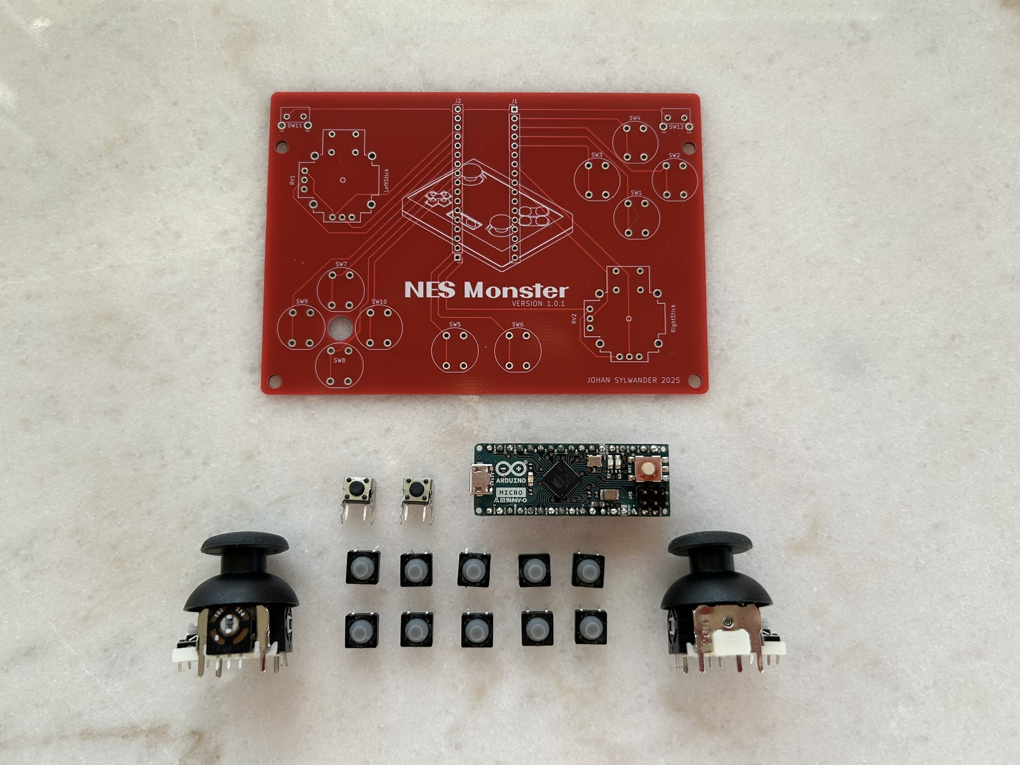
After soldering the components to the board, everything was ready for final assembly.
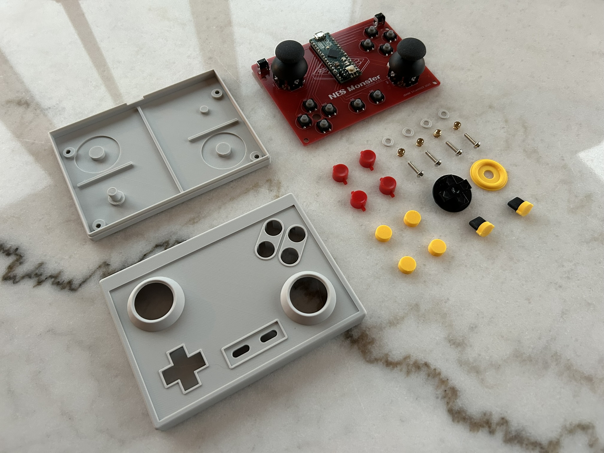
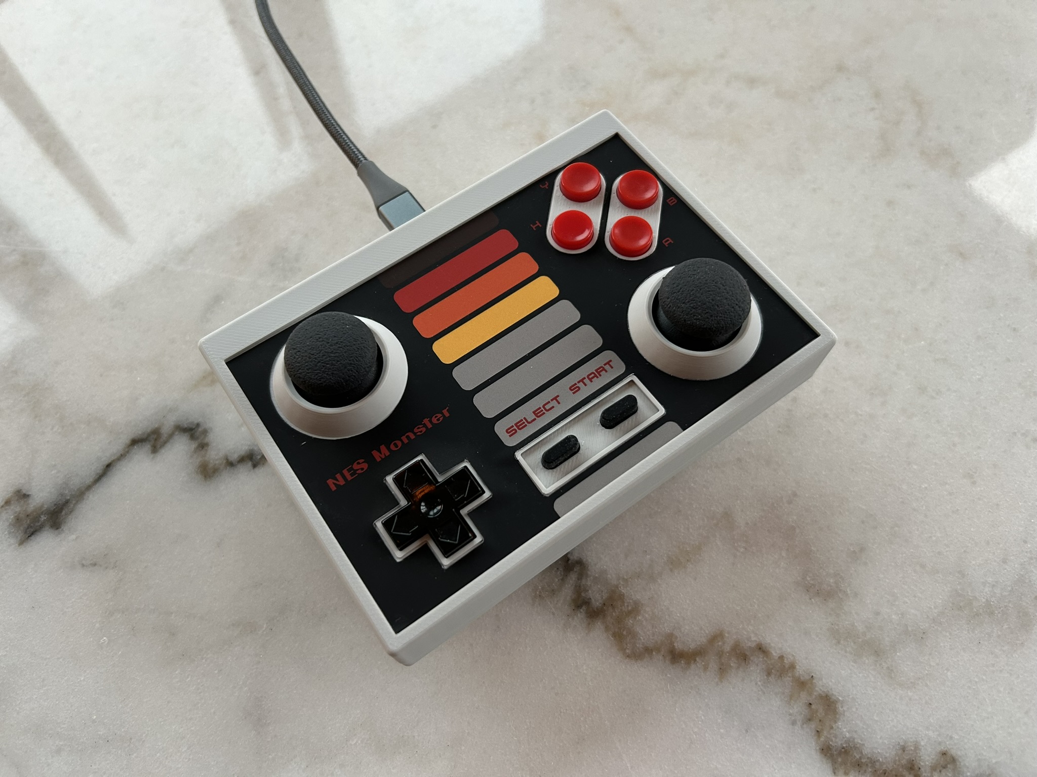
I created the top decal and ordered it from an online sticker service. The quality was great, with punchy colors and exact measurements. Cutting out the holes for the protruding parts on the top was nerve-racking since one small mistake would mean starting over on another sticker. It took about an hour cutting extremely carefully with a scalpel.
And here it is, the NES Monster game controller!
The code required to make the Arduino act as an XInput device is quite short and simple. It just enumerates all buttons and joysticks, sets modes on the relevant pins and then reads those pins every loop step and passes them on to XInput. XInput then sends this information to the connected host:
#include <XInput.h>

///////////////////////////////////////////////////////////////////

// Digital input pins:

#define ButtonSelect    14
#define ButtonStart     15

#define ButtonA         9
#define ButtonB         10
#define ButtonX         8
#define ButtonY         11

#define DPadUp          21
#define DPadDown        22
#define DPadLeft        20
#define DPadRight       23

#define ShoulderLeft    7
#define ShoulderRight   12

#define JoyLeftX        A0
#define JoyLeftY        A1
#define JoyRightX       A7
#define JoyRightY       A6

#define JoyStickMax     1023

///////////////////////////////////////////////////////////////////

void setup()
{
    Serial.begin(115200);

    XInput.setAutoSend(false);
    XInput.begin();

    XInput.setJoystickRange(0, JoyStickMax);

    pinMode(ButtonSelect, INPUT_PULLUP);
    pinMode(ButtonStart, INPUT_PULLUP);

    pinMode(ButtonA, INPUT_PULLUP);
    pinMode(ButtonB, INPUT_PULLUP);
    pinMode(ButtonX, INPUT_PULLUP);
    pinMode(ButtonY, INPUT_PULLUP);

    pinMode(DPadUp, INPUT_PULLUP);
    pinMode(DPadDown, INPUT_PULLUP);
    pinMode(DPadLeft, INPUT_PULLUP);
    pinMode(DPadRight, INPUT_PULLUP);

    pinMode(ShoulderLeft, INPUT_PULLUP);
    pinMode(ShoulderRight, INPUT_PULLUP);

    pinMode(LED_BUILTIN, OUTPUT);
}

///////////////////////////////////////////////////////////////////

void loop()
{
    // Set all button states before send

    XInput.setButton( BUTTON_BACK,  !digitalRead( ButtonSelect ));
    XInput.setButton( BUTTON_START, !digitalRead( ButtonStart ));

    XInput.setButton( BUTTON_A,     !digitalRead( ButtonA ));
    XInput.setButton( BUTTON_B,     !digitalRead( ButtonB ));
    XInput.setButton( BUTTON_X,     !digitalRead( ButtonX ));
    XInput.setButton( BUTTON_Y,     !digitalRead( ButtonY ));

    XInput.setButton( DPAD_UP,      !digitalRead( DPadUp ));
    XInput.setButton( DPAD_DOWN,    !digitalRead( DPadDown ));
    XInput.setButton( DPAD_LEFT,    !digitalRead( DPadLeft ));
    XInput.setButton( DPAD_RIGHT,   !digitalRead( DPadRight ));

    XInput.setButton( BUTTON_LB,    !digitalRead( ShoulderLeft ));
    XInput.setButton( BUTTON_RB,    !digitalRead( ShoulderRight ));

    XInput.setJoystick(JOY_LEFT, JoyStickMax - analogRead(JoyLeftX), analogRead(JoyLeftY));
    XInput.setJoystick(JOY_RIGHT, JoyStickMax - analogRead(JoyRightX), analogRead(JoyRightY));

    XInput.send();

    // Signal button presses through onboard LED

    bool ButtonDown = false;
    for (uint8_t i = 0; i <= TRIGGER_RIGHT; ++i)
    {
        if (XInput.getButton(i))
        {
            ButtonDown = true;
            break;
        }
    }

    digitalWrite(LED_BUILTIN, ButtonDown ? HIGH : LOW);
}

///////////////////////////////////////////////////////////////////
This project was incredibly fun to work on and I learned a lot by taking it all the way to fully functional.
Leave a Reply